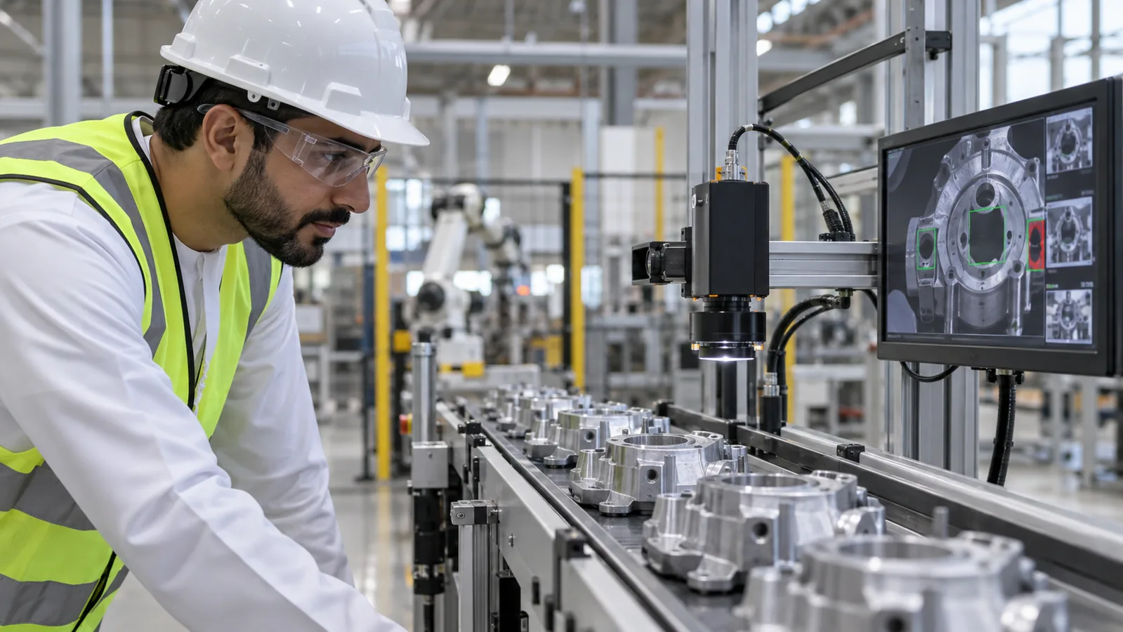
AI industrial vision inspection uses cameras, controlled lighting and a trained model running near the line to classify or locate defects on parts and packaging in real time. It complements classic rule-based machine vision when defects vary in appearance. Results drive a PLC reject signal and are written to MES or ERP for traceability. Image quality and labelled examples decide accuracy far more than the model does.
Swedish Technology builds vision inspection as an engineered system — optics and lighting first, then the model, then the PLC and MES integration — with a measured accuracy report before anyone signs off on production use.
What problem does this solve?
Visual quality checks are the part of production that scales worst. An operator looking at parts for a full shift will find obvious defects reliably in the first hour and progressively less after that, and two operators rarely agree on borderline cases. When the line speeds up, sampling replaces full inspection, and the defects that escape are discovered by the customer instead of by the plant. In regulated sectors — food, pharma, packaging for export — the missing part is not only the detection but the record proving that each unit was inspected.
Many plants already own a classic machine vision system and are disappointed with it. Rule-based vision is excellent when the defect is a measurable geometric fact: a hole out of tolerance, a missing cap, a label offset by more than two millimetres. It becomes brittle when the defect is a class of appearance rather than a measurement — scratches on brushed metal, weld porosity, contamination on a textured surface, print smearing, colour drift. Every new product variant then needs another threshold, and the tuning work never ends.
The third failure mode is organisational. A vision cell is bought as a black box, the integrator leaves, and nobody in the plant can add a new defect class, retrain the model or explain to an auditor why a unit was rejected. Six months later the system is running with alarms disabled because it produces too many false rejects, and the quality team is back to manual checks with an expensive camera watching.
How the solution works
An AI vision inspection system treats the problem in the correct order: first make the defect reliably visible to a camera, then train a model on real production images, then wire the decision into the line and the plant systems. The imaging work — lens, working distance, resolution per defect feature, lighting geometry (bright field, dark field, diffuse dome, backlight), trigger and part presentation — decides most of the achievable accuracy, and no model recovers information that the optics never captured. Once images are consistent, a classifier, object detector or segmentation model is trained on labelled examples, validated on a held-out set, and deployed to an industrial edge computer next to the line so that decisions are made in cycle time without depending on a network link.
The output is not just a pass/fail. Each inspection produces a decision, a confidence value, a defect class and a stored image, which goes to the PLC as a reject signal and to MES or ERP as a traceable record against the batch, lot or serial number. Operators can review borderline cases in a queue; their corrections become new training data. Swedish Technology develops these systems as custom engineering projects and hands over the trained model, the labelling dataset, the retraining procedure and the integration code, so the plant can extend the system without depending on us.
- 1Input / trigger A photo-eye, encoder pulse or PLC signal tells the camera exactly when the part is in position, so every image is taken from the same pose at the same point on the line.
- 2Capture An industrial camera (GigE Vision / USB3 Vision, area or line scan) captures under controlled lighting. Exposure, gain and light geometry are fixed and documented; ambient light is shielded because it is the most common cause of a system that works in the morning and fails at night.
- 3Pre-processing The edge node crops the region of interest, corrects distortion, normalises brightness and, where the part can move, locates the part first so the defect model always sees the same framing.
- 4Inference The trained model runs on the edge device (GPU or NPU accelerated, typically ONNX Runtime or TensorRT) and returns a class, defect boxes or a defect mask with a confidence score, in a few milliseconds to tens of milliseconds per image.
- 5Decision & integration A decision layer applies your thresholds and business rules — reject, divert, mark for manual review, or stop the line — and signals the PLC over digital I/O, OPC UA or fieldbus. The same event is posted to MES/ERP with batch, lot and defect code.
- 6Action The rejector, diverter or robot acts within the line's time window; the operator HMI shows the defect image and reason so the shift can act on the cause, not just remove the part.
- 7Reporting & learning Defect rates by class, shift, machine and product variant are reported; images from uncertain or disputed decisions collect in a review queue and feed the next retraining cycle, with model versions recorded for audit.
Reference architecture
Keep inference at the line, keep training separate, and keep the plant systems as the record of truth. A workable layout has five layers.
| Layer | What it contains |
|---|---|
| Optics & illumination | Camera, lens and lighting selected for the smallest defect that must be caught, with a stated resolution budget (pixels per millimetre of defect feature), fixed mounting, shielding from ambient light and a cleaning regime for lenses and windows in dusty or wet environments. |
| Acquisition & trigger | Machine-vision interface (GigE Vision/GenICam), hardware trigger from encoder or sensor, timestamping, and image buffering so no frame is lost when the line runs fast. |
| Edge inference | Industrial PC or embedded GPU/NPU device in the panel, running the model plus pre/post-processing, a local image store, health monitoring and a watchdog. Operates without internet; a network outage must never stop the line. |
| Decision & control interface | Thresholds, hysteresis, N-of-M rules and safe defaults; connection to the PLC via digital I/O, OPC UA or the plant fieldbus, with a documented fail-safe behaviour when the vision system is unavailable. |
| Data, MES/ERP & MLOps | Inspection records to MES/ERP (batch, lot, serial, defect code, image reference), a dashboard for quality, and a training environment on-premise or in a private cloud holding the labelled dataset, model versions and evaluation reports. |
Deployment options: Everything needed for production runs inside the plant network: edge node at the line, training server in the data centre, no dependency on an external service. Where a customer prefers a private cloud in the UAE for training and dashboards, only images that the customer approves for export leave the site; fully air-gapped installations are supported with offline model updates on removable media.
Key capabilities
Integrations
The vision system must be a good citizen on the plant floor: fast and deterministic towards the PLC, and well-structured towards the plant's record systems. Integration work is custom development against the customer's own interfaces.
| System | Integration point & data exchanged | Direction |
|---|---|---|
| PLC / line control (Siemens, Rockwell, Beckhoff) | Reject, divert or stop signals over digital I/O, OPC UA or the plant fieldbus, with heartbeat and fail-safe behaviour defined in writing. | bi-directional |
| MES / production execution | Inspection results, defect codes and image references written per unit or batch; product recipe and variant read back so the correct model and thresholds are loaded automatically. | bi-directional |
| SAP / Oracle / Odoo (quality and inventory) | Quality notifications, scrap and rework postings, and lot-level defect summaries created from inspection events through a service layer. → Predictive Maintenance AI for Industrial Assets | outbound |
| Historian / time-series database | Defect rates and machine parameters stored together so quality trends can be correlated with process settings and maintenance events. | outbound |
| Existing CCTV / camera infrastructure | Where inspection is not per-part but area-based, ONVIF/RTSP streams can be reused for process and safety analytics instead of new cameras. → Site Safety Computer Vision (PPE, Zones, Vehicles) | inbound |
| Business intelligence and reporting | Defect KPIs by line, shift, supplier and product variant published to the plant's BI layer for management review. → Business Intelligence | outbound |
Industry use cases
UAE & GCC considerations
Production images are commercially sensitive and, in defence-adjacent or government-owned plants, classified. Every element required for production inspection in our designs runs inside the plant: the edge node, the model and the image store, with training on an on-premise server or a UAE-region private cloud under the customer's control, and air-gapped installations supported through offline model delivery. Operator interfaces, defect naming and training material are delivered in Arabic and English so that line staff, quality engineers and auditors work from the same vocabulary. Procurement in the UAE and wider GCC usually expects a fixed-scope feasibility study or paid pilot with a measured accuracy report before a full line roll-out, a documented hand-over including the dataset and retraining procedure, and local support with response times written into the contract — all of which we scope explicitly rather than leaving to a maintenance agreement.
Implementation approach
- 1Feasibility (1–3 weeks) Define the defects in words and pictures, agree what a 'defect' actually is with the quality team, review sample parts and existing images, and state whether the defect is detectable at all with reasonable optics.
- 2Imaging trial Test lens, working distance and lighting geometry on real good and bad parts, at the line's speed if possible. This step decides the project; a poor imaging setup cannot be fixed later with a bigger model.
- 3Data collection and labelling Collect images across shifts, product variants, materials and lighting conditions; label with the quality team using an agreed defect taxonomy. Rare defect classes may need parts collected over weeks or produced deliberately.
- 4Model training and evaluation Train and validate on held-out data; report false-reject and false-accept rates per defect class at chosen thresholds, and agree the operating point with the quality manager, not with the data scientist alone.
- 5Integration build Edge node installation, PLC signalling, MES/ERP interface, operator HMI, image archiving and retention rules, alarm and health monitoring.
- 6Shadow run (2–6 weeks) The system inspects and records but does not reject. Its decisions are compared with the current inspection process, disagreements are reviewed, and thresholds are adjusted with real evidence.
- 7Go-live and acceptance Switch to active rejection with agreed acceptance criteria, operator training in Arabic and English, and documented fail-safe behaviour.
- 8Hand-over and retraining cycle Source code, model artefacts, labelled dataset, retraining runbook and a schedule for periodic re-evaluation as products and materials change.
Security & deployment
The inspection cell sits on the plant network, not on the office network, and communicates with MES/ERP through a defined interface rather than direct database access. Edge nodes run a hardened OS with signed model artefacts and a versioned deployment, so an auditor can establish exactly which model version made a given decision. Image archives are subject to a retention policy agreed with the customer, since they can contain product and process information; access to review queues and to the retraining environment is role-based. Where the plant policy requires it, the whole solution operates without any outbound internet connection, with model updates delivered as signed packages on approved media.
Limitations & prerequisites
- If the defect is not visible in the image, no model will find it. Sub-surface flaws, internal cracks or contamination under an opaque layer need X-ray, ultrasound or thermography, not a normal camera.
- Accuracy depends on labelled examples. Rare defect classes are the hardest: a defect that occurs a few times per year cannot be learned from a two-week data collection, and anomaly-detection approaches trade that for a higher false-reject rate.
- There is always a trade-off between false rejects and missed defects. Pushing missed defects towards zero raises the number of good parts thrown away; the operating point is a business decision, not a technical constant.
- Changes to the product, material, supplier, lighting or camera position can silently degrade accuracy. Periodic re-evaluation and a monitoring plan are part of running the system, not an optional extra.
- Line-speed and cycle-time limits are real. Very fast lines may need line-scan cameras, multiple cameras, or a smaller model, and some inspections cannot be done in the available window at all.
- Environmental conditions — dust, steam, vibration, wash-down, heat — affect optics more than they affect software. Enclosures, air purge and cleaning routines have to be budgeted.
- The system reports what it sees; it does not explain the root cause. Linking defect classes to process parameters is a separate analytics exercise.
Manual inspection vs rule-based machine vision vs AI vision
These three are not competitors; most plants end up with a combination. The question is which defect belongs to which method.
| Criterion | Manual inspection | Rule-based machine vision | AI vision inspection |
|---|---|---|---|
| Best suited to | Low volume, varied products, judgement calls | Measurable geometry and tolerances | Defects defined by appearance, not measurement |
| Consistency across a shift | Degrades with fatigue | Fully consistent | Fully consistent |
| Handling new product variants | Immediate, with instruction | Re-tuning thresholds per variant | Retraining or fine-tuning with new images |
| Data needed before it works | None | Reference geometry and tolerances | Labelled images of good and defective parts |
| Explaining a rejection | Operator judgement | Deterministic rule and measurement | Defect image, class and confidence; less deterministic |
| Traceability record per unit | Rarely captured | Measurement values | Decision, class, confidence and image |
| Typical failure mode | Missed defects late in a shift | Brittle to appearance variation | Silent drift when the process or optics change |
| Ongoing effort | Labour cost per shift | Tuning at every product change | Monitoring, periodic retraining, dataset upkeep |
A pragmatic plant keeps calibrated measurement in rule-based vision, gives appearance defects to the AI model, and keeps a human review queue for the borderline cases that neither method should decide alone.
FAQ
Four things: the number of inspection points and cameras, how difficult the imaging is (a defect needing special lighting or line-scan optics costs far more than a well-lit label check), how much labelling is required and whether defect samples exist, and the depth of PLC/MES/ERP integration. Hardware is usually the smaller part; imaging engineering and data work dominate.
Feasibility and imaging trials take 2–5 weeks. Data collection is the long pole and depends on how often defects occur — typically 3–8 weeks. Training, integration and a shadow run add 6–12 weeks. A single well-defined inspection point can reach production in about three months; a multi-camera, multi-defect line takes longer.
As a working rule, a few hundred clear examples per defect class, spread across shifts, variants and materials, gives a usable first model; a few dozen may be enough to prove feasibility. If defects are extremely rare, we start with an anomaly-detection approach trained mainly on good parts and accept a higher false-reject rate until real defects accumulate.
Yes, and for production inspection it should. Inference runs on an edge node at the line with no internet dependency, training runs on an on-premise server or a private cloud you control, and model updates can be delivered as signed offline packages for air-gapped plants.
None before the imaging trial, and we will not quote a percentage in a proposal. After the trial and a labelled dataset we report measured false-reject and false-accept rates per defect class at several thresholds, and you choose the operating point. Anyone quoting a fixed accuracy figure for your parts before seeing images is guessing.
In most installations it changes their work rather than removing it. The system handles the repetitive full-rate screening; operators handle the review queue, the root-cause work and the exceptions. Plants that plan for a review role get better models, because operator corrections are the training data.
Through a service layer that writes inspection events — unit or batch identifier, decision, defect code, confidence, model version and image reference — into MES, and creates quality notifications or scrap postings in SAP, Oracle or Odoo. The vision node never holds ERP credentials. Interfaces are agreed as a written contract of fields and directions before development starts.
You do. The labelled dataset, trained model artefacts, training scripts and integration source code are handed over, together with the retraining runbook. We can maintain and retrain the system under a support agreement, but the plant is never locked out of its own quality system.
The fail-safe behaviour is defined during design and tested during commissioning — typically the line continues with a documented alarm and fallback to manual sampling, or halts, depending on the product risk. The PLC interface includes a heartbeat so a frozen vision node is detected rather than silently passing everything.
Not sure the defect is even visible to a camera?
Send us sample images or a short video of the line and a description of the defects you need caught. We reply with a written feasibility view: optics and lighting needed, data required, realistic accuracy range, and whether classic machine vision would do the job cheaper.
Request a Vision Inspection Feasibility StudySources & evidence
- EMVA — EMVA 1288 standard for characterisation of image sensors and cameras — camera performance measurement
- EMVA — GenICam generic interface for cameras
- OPC Foundation — OPC UA — edge-to-PLC and edge-to-MES interfacing
- ONNX Runtime — documentation — model deployment on edge hardware
- NIST — AI Risk Management Framework — governance of deployed AI decisions
Vendor and product names are trademarks of their respective owners; references are for technical context and do not imply partnership, certification or endorsement unless stated on the vendor's official pages.